
User Interface
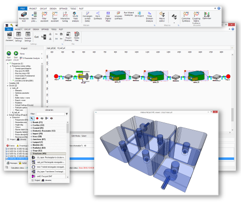
µWave Wizard™ features a ribbon type User Interface (UI), offering a user friendly desktop
environment with the familiar appearance and convenience of office software. Intuitive icon type shortcuts and editors, distributed across the ribbons, help understand each task more quickly.
Tabs for Project, Circuit, Design, Optimizer, Tools and Plots are easily accessible.
The Project Tree View provides all information about the project such as frequency settings, variables, circuits including sub-circuits and default settings
like units, accuracy, symmetries and material properties. The UI features separate identification of variables belonging to a selected circuit.
µWave Wizard's™ schematic editor allows the creation of three-dimensional structures based
on key building blocks.
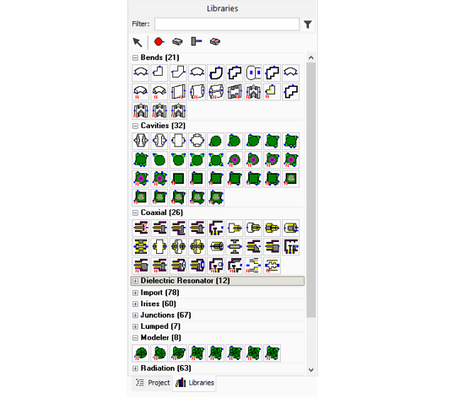
Libraries
µWave Wizard™ contains predefined full-wave parameterized building blocks and the number of elements is continuously
growing (so far, more than 450 elements).
The modeler uses special modeler elements. These elements are managed in the same manner like the predefined elements from the libraries and are connected multimodal at their ports with other elements. The user can specify geometries of a model with variables. These variables appear as parameters in the µWave Wizard™ element editor and can be part of an optimization.
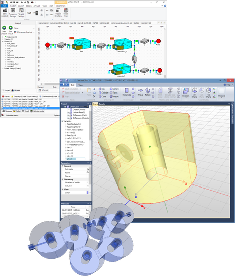
Modeler
µWave Wizard's™ graphic modeler is directly accessible through µWave Wizard's™ modeler library. The integrated modeler is a versatile 3D editor capable of creating and modifying geometrical models of 3D and planar structures which offers a different design approach.
Complex geometries are created from simple objects like e.g. boxes, cylinders or rectangles and are then modified and/or subjected to Boolean operations (union, subtraction, intersection). In other words a two-dimensional cross-sectional profile is created using 2D primitives and this profile is then extruded along a line to create a 3D structure.
Whenever an object is created or modified, the action is added to the list of Constructive Solid Geometries (CSG-Tree). This simplifies and speeds up the designs and further simplifies possible modifications of the structures.
Other features for construction include creation of arrays of objects using the cloning tool, fillets to create accurate models of devices manufactured with machining radii, and creating structures with ruled surfaces.
The modeler also provides a simple and powerful way to modify structures once they have been built. Thanks to parameterization of all operations related to geometries, the dimensions and other parameters of structures can be quickly modified, so there is no need to build the structures again. The desired operation is easily selected on the editor and new parameter values can quickly be entered or changed. The structure is then rebuilt automatically according to the new parameters.
Moreover, a flexible variable mechanism is incorporated into the modeler enabling not only the introduction of simple numerical values but also complex equations, utilizing a range of built-in predefined functions.
Design flexibility is achieved by utilizing multiple nested coordinate systems. All variables are synchronized between the modeler and µWave Wizard's™ UI. The connection between modeler elements (even for complex structures) is supported by the multimodal scattering matrix. No normalization or manual sorting of modes is necessary. The corresponding waveguide ports between the elements simply have to be connected inside the schematics.
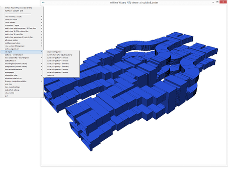
3D-Viewer
µWave Wizard's™ 3D viewer displays schematics, mesh, field and pattern plot files. There are no limitations regarding model size
and complexity. It supports the design of the most complex components, regardless of the individual coordinate systems of their key building blocks. The 3D viewer shows the interconnection of
elements or sub-circuits. Misalignments and erroneous connections will be indicated within the 3D-plot window. Export of CAD files in STL, STEP, IGES or DXF format enable portability between
graphical design platforms and can also be used for controlling CNC tools.

Macro Editor
The macro editor contains predefined VBA macros for the COM interface, i.e. for generating taper structures, automatic connection and convergence analysis. Using the built-in VBA editor, the set
of macros can be easily extended, i.e. to create links to external programs such as MATLAB® or Excel®.