
Synthesis Tools

µWave Wizard™ offers a variety of different synthesis tools. These tools are helpful to get directly from a specification to a µWave Wizard™ schematic. All necessary elements are placed in the schematics editor and all parameters (typically all dimensions) are set automatically according to the specifications. This approach is very useful for quickly obtaining an estimate of the size matrix and the size of the structure. Furthermore, the dimensions can be used as very good starting values for a subsequent optimization.
µWave Wizard™ supports:
• Bandpass Filter Synthesis
• Lowpass Filter Synthesis
• Interdigital Filter Synthesis
• Taper Synthesis
• Horn Antenna Synthesis
• Reflector Antenna Synthesis

Bandpass Filter Synthesis
The filter synthesis assistant automatically generates Chebyshev- or Butterworth bandpass filter models based on user specifications. A built-in spline interpolation algorithm significantly
accelerates the calculation of inverter values. The synthesis process creates a complete 3D model of the filter. It also generates a schematic containing the set of geometries necessary to build
the filter. The geometries are parameterized to allow for manual changes or automated optimization.
One project can include several synthesized filters in form of sub-circuits, a convenient feature for multiplexer designs. Individual filter channel specifications are automatically assigned to
goal functions of the respective sub-circuit. Channel specific optimization goals can be selected and shared between individual filters or can be used to create optimization goals for the entire
multiplexer. This approach not only simplifies analysis and optimization of a multiplexer assembly, it also allows for conducting performance studies comparing RF performance of different filter
topologies derived from for the same specifications.

Lowpass Filter Synthesis
µWave Wizard™ includes a user friendly lowpass filter synthesis tool. This tool creates a complete 3D model of
a lowpass filter and a schematic containing the set of geometries necessary to build the filter. The schematic includes a goal function derived from user specifications. The geometries within the
schematic are parameterized to allow for manual changes or optimization. Due to the proximity of discontinuities within the filter, high order mode interaction can occur and impact RF
performance. Because the synthesis tool only assumes fundamental mode connection, in rare cases a brief post optimization may be required where µWave Wizard™ takes higher order modes into account.
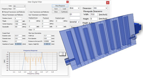
Interdigital Filter Synthesis
The interdigital filter synthesis tool allows creating interdigital filter geometries in just a few steps. Desired filter parameters need to be specified (filter order, insertion loss,
ripple level, bandwidth, etc.), followed by the input and output geometries of the filter and the dimensions of the coaxial ports. Analysis and optimization of the synthesized filter are
supported.

Taper Synthesis
For a taper (transformer) synthesis, the user can choose between a Taper Assistant or a taper VBA synthesis template.
The result of the taper synthesis is an automatically generated, complete schematic. This includes the setup of the variables including extensions.
All input values of the Taper Assistant are saved in a special file format which can be reloaded and modified to different specifications again.
As a result a second taper can be generated based on a previous design.
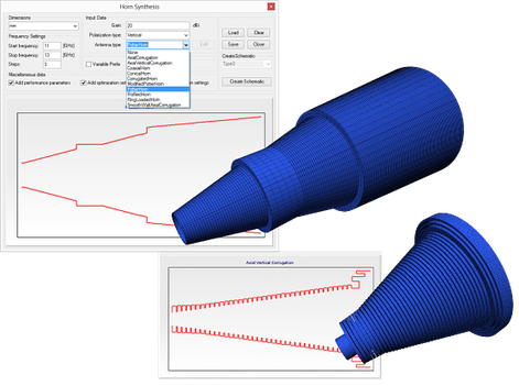
Horn Antenna Synthesis
The horn antenna synthesis tool supports synthesis of typical horn antennas. The synthesized horn antenna profiles are computed by µWave
Wizard's™ Body Of Revolution (BOR) horn antenna elements. Analysis and optimization of multimode and tracking horn designs are supported.
The synthesis tool offers choices for selecting from the following profiles: Conical horns, dual mode horns (Potter horn), modified Potter horn, profiled smooth wall horn, corrugated horns with
corrugation perpendicular to the horn axis, ring loaded corrugated horns, corrugated horns with axial corrugations, coaxial waveguide corrugated horns and hybrid geometry horns with axial and
vertical corrugations. As a result, the schematic of the entire structure is automatically generated and commonly used performance parameters are assigned as optimization goals.
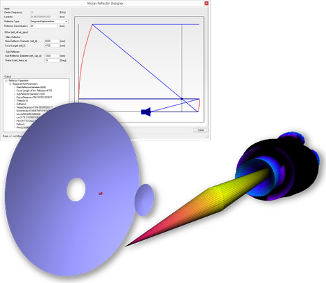
Reflector Antenna Synthesis
The reflector synthesis tool is capable of designing several reflector and sub-reflector types ranging from very basic structures like parabolic and hyperbolic to more complex structures such as
Displaced Axis (DAX) Cassegrain/Gregorian reflectors. This tool also offers the option of creating any user defined reflector or sub-reflector.
The incident EM-field on the reflector is calculated using spherical wave expansion of the radiated horn antenna field. The calculation of the far field of basic reflectors such as paraboloid,
hyperboloid and ellipsoid is being performed by Physical Optics (PO) approximation. The radiated reflector field is also available as spherical-wave-expansion, which can be applied as feeding
system into other reflectors. The definition of the reflector geometry is completed by just a few parameters only. The automatic mesh generation is supported by the simulation kernel.